If your ground rods are placed at least one rod length apart you can use a formula to estimate the earth resistance of multiple grounding rods.
Ground rod resistance check.
For example the national electric code requires no greater than 25 ohms of resistance in a ground system.
Ground ring ground rods.
R loop 10 ω 0 17 ω 10 17 ω.
Ideally a ground should be zero ohms of resistance but.
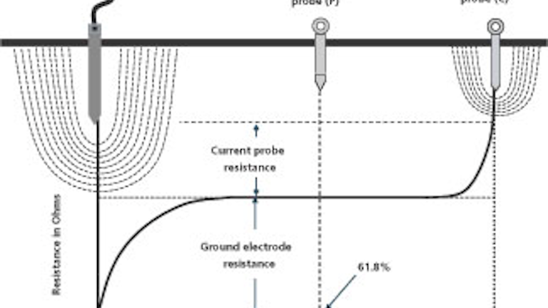
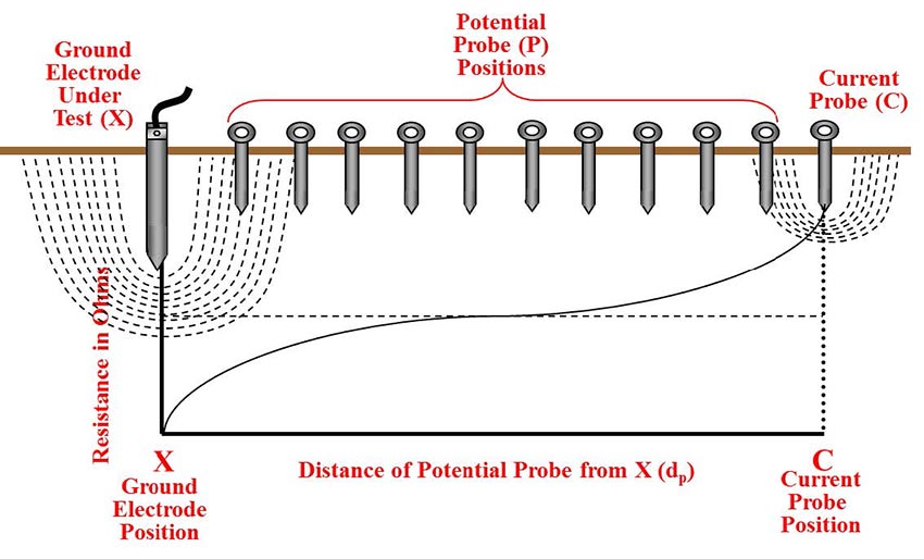
You can only do this by using the fall of potential method with a three terminal earth ground resistance tester.
Step 1 connect your length of wire to a metal stake in the ground.
In some instances ground rods can be installed in areas where the earth has a lot of resistance.
So if you are using 10 foot ground rods you must place.
Run the wire to your test location.
If there were 60 similar ground electrodes with a resistance of 10 ω each the measurement of the total loop resistance would be.
An ideal ground rod resistance should be below 3 ohms.
You should measure the resistance of an electrode with respect to the surrounding soil in the area.
P2 and c2 connect to a separate all metallic grounding point like a water pipe or building steel.
Make sure that you have stripped back the insulation from both ends of the wire to allow for a good connection.
Step 5 measure the ground or leakage current if you wish to find out about the ground or leakage current all that you have to do is to set the rotary switch to ma or a.
However we can estimate the resistance to ground using scenario b.
The measurement of the loop resistance is relatively close to the resistance of the ground electrode being tested.
Unfortunately there is not one standard ground resistance threshold recognized by all certifying agencies.
For instance if a ground rod is driven into a very rocky and dry area it may not conduct electricity into the ground well.
Multiple ground rods yield a lower resistance to ground than a single rod.
The lower it is the better job it does.
The nfpa and ieee recommend a ground resistance value of 5 ohms or less while the nec has stated to make sure that system impedance to ground is less than 5 ohms specified in nec 50 56.
For a safe electrical system your ground rod resistance should have a very low resistance value.
Unfortunately as time goes by factors such as ground rod corrosion soil moisture high salt content high temperatures and loss of contact of your wires as well as others may increase the resistance of ground rod s hence affecting its effectiveness.
With this method the resistance of two electrodes in a series is measured by connecting the p1 and c1 terminals to the ground electrode under test.
To properly test the resistance of a ges you must follow some simple rules.